![]()
|
|
|
![]() MICROGRAVITY FACILITIES FOR COLUMBUS
DIVISION
MICROGRAVITY FACILITIES FOR COLUMBUS
DIVISION
|
Fluid Science Laboratory (FSL) |
![]() Introduction
Introduction
The Fluid Science Laboratory (FSL) is a multi-user research facility on board the Columbus Laboratory (COF) dedicated to investigations in fluid physics under microgravity conditions. It can be operated in a fully automatic or semi-automatic mode on the station by the flight crew or remotely controlled from ground in the so called tele-science mode.

The design concept of the FSL facility is based on user requirements as well as the Space Station utilisation requirements and constraints. This essentially resulted in a highly modular concept allowing for continual upgrades of the system capabilities throughout its defined operational life-time. All these drawer-like modules are integrated in an International Standard Payload Rack (ISPR).
The main elements of the FSL payload system are:
![]() Facility Core Element (FCE), comprising:
Facility Core Element (FCE), comprising:
Optical Diagnostics Module (ODM)

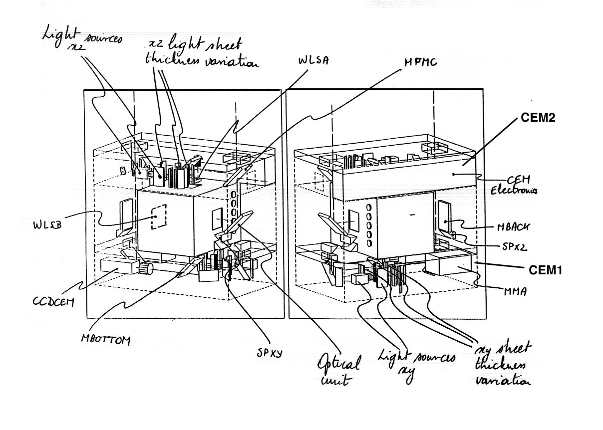
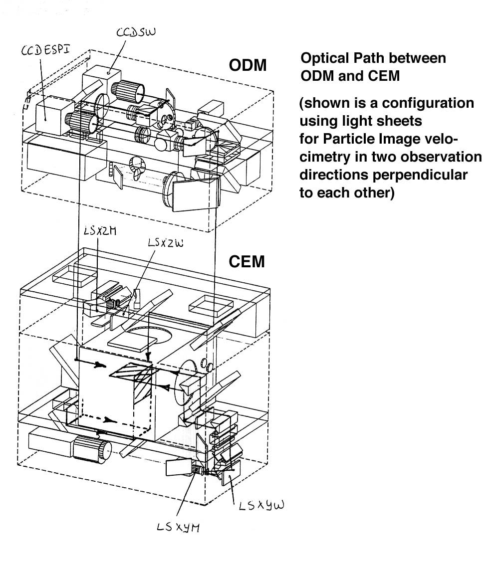
The Facility Core Element (FCE) represents the processing and diagnostics kernel of the facility and comprises three modules (ODM, CEM1 and CEM2, see below) which are mounted and optically aligned to each other within a CFRP frame structure:
The Optical Diagnostics Module
The Optical Diagnostics Module (ODM) carries the equipment for visual and interferometric observation and diagnosis, illuminations, related control electronics and the attachment and functional interfaces for the Front Mounted Cameras for dedicated purposes (e.g. High Speed, High Resolution, Infrared).
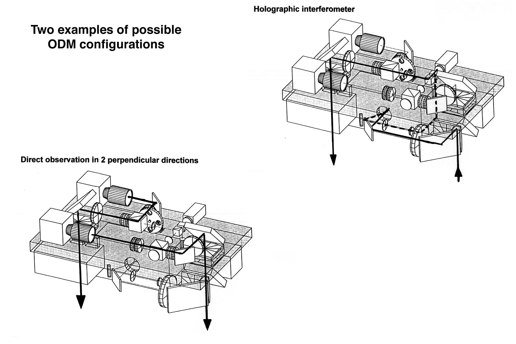 The
optical equipment, laser sources, CCD cameras, aperture wheel, etc. are defined
as On-orbit Replaceable Units (ORU's). Different types of interferometric
measurements can be applied, as there is an Electronic Speckle Pattern
Interferometer (ESPI) for transparent and reflective measurements, a
differential interferometer and a holographic interferometer. In addition a
Schlieren observation mode is available. The instrument hardware could be kept
to a minimum as the different types of interferometers can be converted into
each other.
The
optical equipment, laser sources, CCD cameras, aperture wheel, etc. are defined
as On-orbit Replaceable Units (ORU's). Different types of interferometric
measurements can be applied, as there is an Electronic Speckle Pattern
Interferometer (ESPI) for transparent and reflective measurements, a
differential interferometer and a holographic interferometer. In addition a
Schlieren observation mode is available. The instrument hardware could be kept
to a minimum as the different types of interferometers can be converted into
each other.
For a total overview of the available diagnostics, see under Standard and Complementary Diagnostics below.
 The
Central Experiment Module (CEM) is subdivided into two parts:
The
Central Experiment Module (CEM) is subdivided into two parts:
CEM1 contains the suspension structure for the Experiment Container (EC) including all functional interfaces (power, data, cooling, etc.), optical equipment such as laser sources and CCD cameras (complementary to the ODM equipment), in addition tiltable mirror assemblies, light sources for background and sheet illumination, the light wells to the ODM, and the Microgravity Measurement Assembly (MMA). This module is designed as a drawer to be pulled out for insertion of the EC.
CEM2 carries supporting diagnostic equipment, a laser source for e.g. light scattering applications, the equipment for light sheet thickness variation, mirror assemblies, and the control electronics to command and monitor the electro- mechanical and opto-mechanical components.
The Experiment Containers (EC's) represent the exchangeable individual experimental equipment. Also here modularity shall allow for a certain reuse of components. They contain the experiment fluid cell, or better the whole experiment fluid loop with all the actual stimuli. Dedicated special diagnostics complementary to the ODM standard equipment and dedicated subsystems necessary to carry out the experimental measurements in mind, can also be introduced on EC level. EC's for various experiments and/or experiment classes will be developed under ESA contract as well as by national space agencies in close cooperation with the scientists and following their approved experiment proposals.
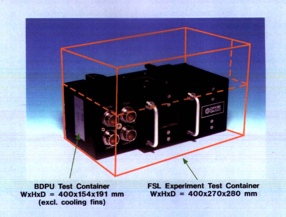
For operation the EC is hosted inside the CEM1 which provides the necessary interfaces. The outer volume of the EC is approximately 30 litres (W x H x D = 400 x 270 x 280 mm).
The following diagram shows the insertion/extraction of the Experiment Container into the CEM:
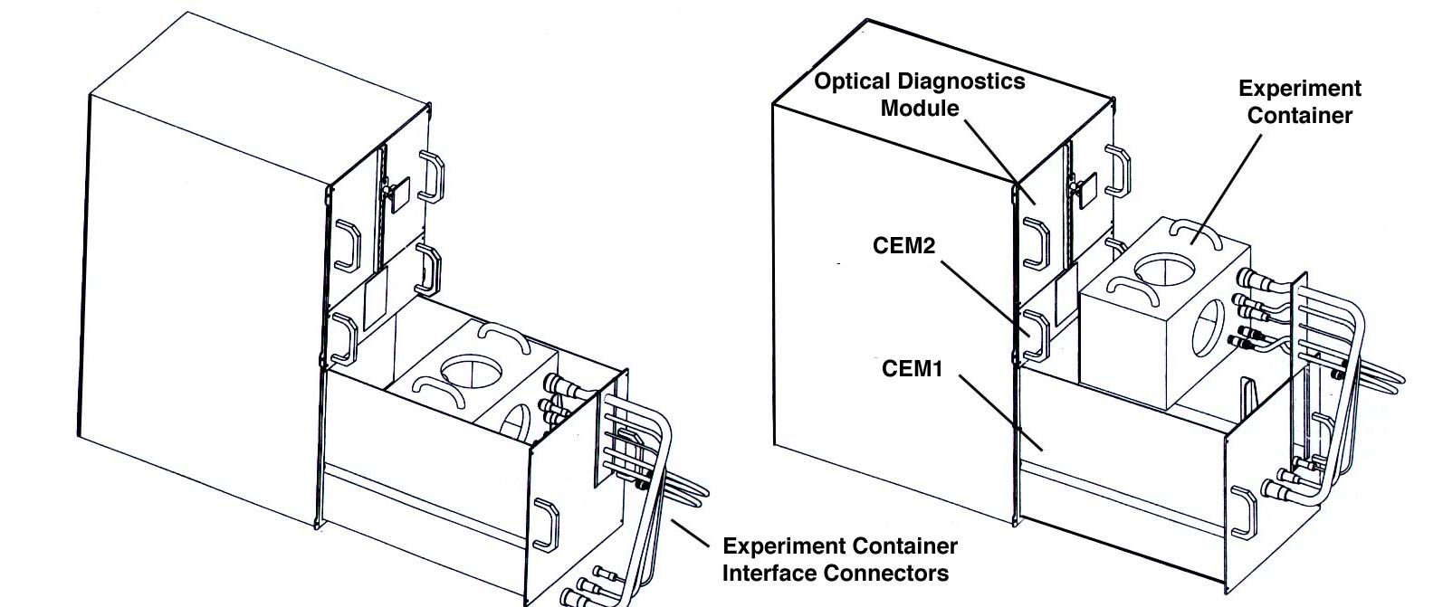
During non-operational phases the EC's are stowed at dedicated location in the Columbus Laboratory.
Compared to the Test Containers of the BDPU facility, flown earlier on SPACELAB missions, the FSL-EC's provide enhanced features such as increased volume (by a factor of 2), improved ‘intelligence’ and thereby extended research potential. By hosting additional internal hardware and software, the EC can implement advanced data elaboration, internal imaging and other payload-specific processes.
Proportions of BDPU and FSL EC's:
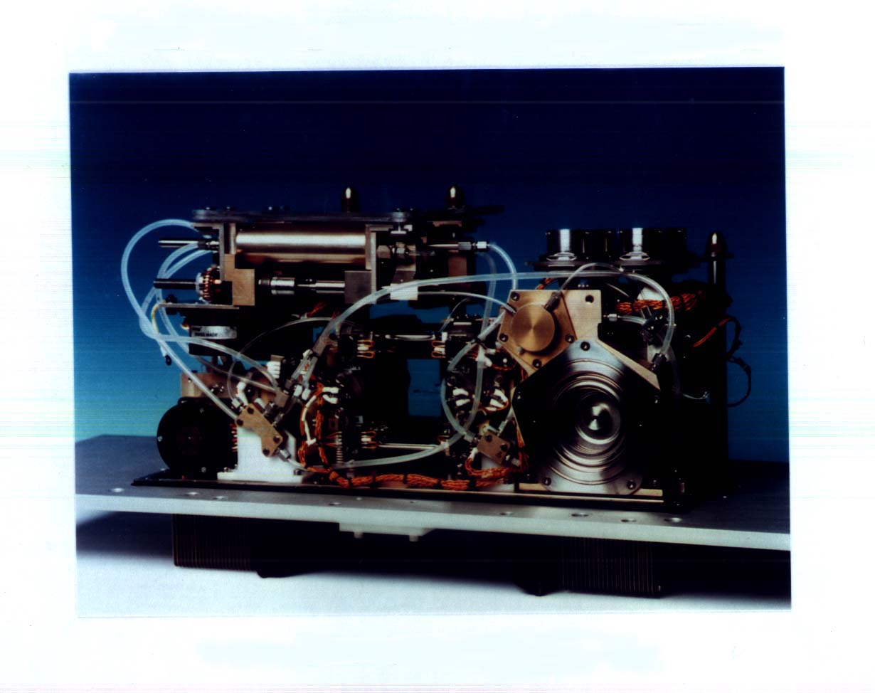
BDPU Test Container assembly for a Bubble Migration experiment (top view without housing)
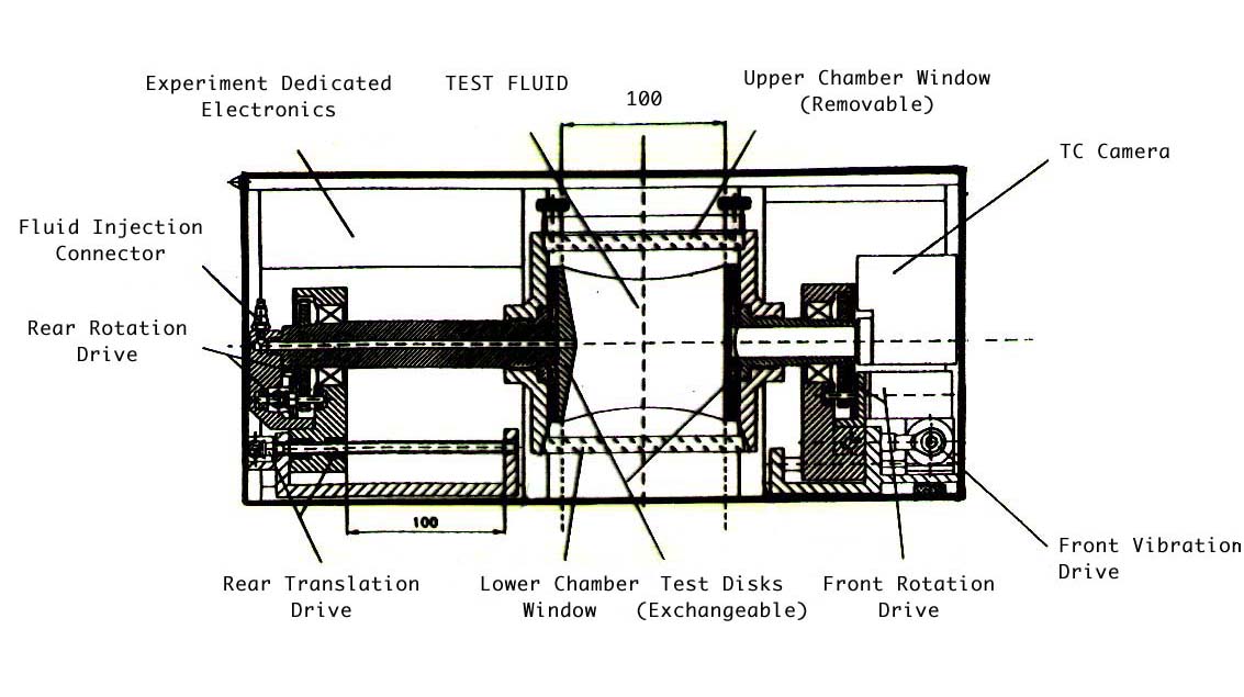
The following diagram is an example of an EC layout for a Fluid Bridge experiment:
To fit within the envelope of the FSL-EC concept, experiments must be designed within the limits of very specific requirements for mass, volume, shape, field of view (FOV), electrical-, thermal- and functional interfaces and safety. Researchers can take advantage of the following interfaces between the FSL facility and the EC:
|
Power lines: 6 DC power lines rated at +28, +15, -15, +12, +5 and -5 V, for an aggregated electrical power up to 300 W. These lines can be used for internal operation and can be activated and deactivated by the experiment software or by the system. | |
|
Low rate data: 1 standard RS 422 interface, used to acquire data inside the EC, or to transmit data/commands to the EC equipment. Maximum transmission rate is 170 Kbps. | |
|
Analog video: 3 lines suited for acquisition of analog camera signals (small camera heads), necessary e.g. for a compact, modular photogrammetric camera front end or a 3-chip colour camera for quantitative colour measurements . | |
|
High resolution digital video: 1 line. This line can acquire digital image data and/or digital sensor data to a total amount of of 240 Mbps . In addition there is of course a sync line for all electronic cameras. | |
|
Pulse commands to the EC: 4 lines suited for transmission of pulses to the EC in order to activate internal hardware. Pulses can be selected between +5, +15 and +28 V, with a duration of 125 ±5 msec. | |
|
Temperature sensors-source monitors: There are 2 interfaces planned which are capable of reading temperature levels internal to the EC. Internal signal conditioning will be provided by the EC itself. | |
|
Digital passive-source monitors: 8 lines which can be used to monitor open/closed states. | |
|
Thermo-electric device driver interfaces: These 4 interfaces (2 high and 2 low) can be used to drive four different Peltier devices for thermal control purposes. | |
|
Analog monitors: 4 lines are provided to acquire analog voltage signals originating from the EC, with the following characteristics: ±5 V (active driver output), 12 bits acquisition resolution and 10 Hz maximum sampling rate. | |
|
Stepper motor driver interfaces: 2 stepper motors can be used inside the EC to drive internal mechanisms of various kinds (positioning systems, injection/extraction devices, etc.) | |
|
Water cooling: 2 "Quick Disconnect", 1/4" diameter, female connectors placed at the EC wall. Water flow characteristics are 30 kg/hr ±10%, average temperature of 21.5° C and heat rejection capability of up to 420 W. | |
|
Experiment observation: The two standard observation directions are centred with respect to the EC volume and perpendicular to each other. Standard field of view is 80x80 mm. |
Overall EC characteristics:
| Dimensions |
| |
| Width | 400 mm | |
| Height | 270 mm | |
| Depth | 280 mm | |
| Mass | Typical | 20-30 kg (40 kg max.) |
| Power consumption | Typical | 100 - 200 W (430W max.) |
| Object space/ inner fluid cell | 1-1000 cc | |
| Experiment object Temperatures | Typical | -5 to 150°, but not limited to those figures (function e.g. of volume, heating/cooling time and safety aspects) |
| Central FOV | 80 x 80 mm | |
| Measurement Channels | Depending on detailed design |
e.g. 16 analog, 8 digital |
| EC housing | Double/triple Containment | Sealed, pressurized, allowing for toxic fluids |
The Front Mounted Cameras (FMC's) can be considered sub-units of the ODM. The purpose of the FMC's is to provide recording means complementary to the integrated CCD cameras for observation of phenomena contained within the fluid cells of the EC in the CEM, with dedicated performance enhancements that can suit both standard and non-standard observations. The FMC's may comprise the following units:
|
Photographic still cameras: Cameras for the 24 x 36 mm – or 6 x 6 cm film format will even in the near future still offer higher spatial resolutions, especially in combination with time resolution, than electronic area sensors. | |
|
High resolution digital cameras: Current chips offer sensor formats of up to 5kx5k. | |
|
High speed cameras: Micro gravity relevant fast fluid science phenomena may require frame rates in the range from 30 to 1000 fps compared to the required standard imaging range of 1 to 30 fps. Recording times of dedicated high speed cameras with an integrated memory are in general short (2-10 s). This problem is expected to be overcome by making use of the latest C-MOS camera technology. | |
|
Infrared camera: A camera with a good low temperature resolution (0.1deg) in combination with a good spatial resolution must be used. (see ‘Fluidpac’) |
Currently, there are a variety of camera types and camera configurations under consideration. The main characteristics under evaluation are number of sensor elements, their size, b/w or colour, storage capacity, sensitivity, maximum frame rate modularity, etc. A final decision will be taken upon approval of the experiment proposals.
Master Control Unit and Laptop Unit
The Master Control Unit (MCU) is the main facility controller, supporting the following principal functions:
|
Management of data communication/exchange with the COF. | |
|
Support to facility operator via the Crew Command Panel (featuring 4 switches and 4 LEDs) and the Laptop Unit, the latter providing the operational man-machine interface. | |
|
Co-ordination of the facility and EC operation and flight/ground operator tasks. | |
|
Monitoring of the facility and EC status. | |
|
On board time synchronisation and information distribution to FSL subsystems. | |
|
Automatic, semi-automatic and "manual" control of facility/experiment operation. | |
|
Data handling, processing, and recording. |
The Laptop Unit (LTU) will serve as the primary interface between the flight crew and the FSL facility. It allows full monitoring and control of both the FSL facility and the experiment process. Crew members can display scientific images from the experiment process as well as information on the status of the facility.
Preliminary overall LTU characteristics: example IBM Thinkpad
| Hardware platform | IBM Thinkpad PC760XD |
| Processor |
Intel Pentium 133 MHz |
| RAM memory | 80 MB |
| Hard Disk capacity | 1.2 GB |
| Screen size | 12.1 in |
| Software | Windows NT Human Computer Interface |
Handling of digital signals and generation and/or handling of digital image signals from EC level, optical diagnostic module level and front panel level (FMC’s) will be done by the Video Management Unit (VMU). This includes the possibilities for multiplexing between different camera sources, digital recording of the full rate up to 240 Mbps (e.g.1000x1000x8bitx30Hz) for about 18 min, parallel recording of the signals, e.g. coming from a photogrammetric camera set (3x512x512x8bitx30Hz=189 Mbps) or a 3-Chip RGB camera.
Dedicated compression techniques, adapted to the characteristics of the scientific images/image classes will allow for a significant extension of the recording time (factor 2 to 20, i.e. 36 to 360min). Higher compression factors will also allow for a qualitative observation in real time on ground (telescience/teleoperation).This will help to make very economic use of the necessarily very limited digital recording capacity in space, which is in any way longer than the 10min of the cine camera of BDPU. A 1kx1k chip is the electronic equivalent to the 16mm film format, with regard to resolution.
Via telescience it will be possible to adapt parameters like frame rate and field of view of interest to the needs of the moment, which leads again to an economic use of the recording capacity.
All digital data come down to the ground as a CCSDS bit stream generated within the VMU, meaning that all image data will be digital ultimately.
It is planned to record in space the very high digital data stream on hard disks operating in parallel. In experiment pauses the disk’s content will be transferred to a digital tape recorder to prepare the hard disks for another real time recording. This also allows for downloading the digital image data physically.
Overall VMU Characteristics:
| Multiplexing between digital sources | Function of total data rate (240 Mbps max.) |
| Recording time for max. digital data rate
(240Mbps) |
18min (30GB on hard diskoperating in parallel) |
| Primary experimental digital data for the detailed scientific evaluation |
transferred during experiment pauses to a
digital tape, physically brought down to the ground |
| Image/data standard |
CCSDS bitstream (max. to ground 32Mbps,
|
| Compression Standard | JPEG under investigation.(Compressor board exchangeable) |
| Images for Telescience |
Image data reduction will be adapted to
qualitative needs. |
| US or EuropeanSync Standard (60/30Hz or 25/50Hz) |
The decision to be made will affect the
given performance only slightly |
| Image Processing | I/F connector at VMU front panel for dedicated image processing. |
The Power Control Unit (PCU) receives the main power at 120 VDC, converts it into the required secondary voltages and distributes these to the individual consumers. This concept avoids converter dissipation at the consumer thus supporting the required minimisation of the thermal dissipation in the highly susceptible FCE and adjacent areas.
The PCU is simultaneously connected to the auxiliary power line which is used in case of main power degradation or loss for an orderly facility shut down.
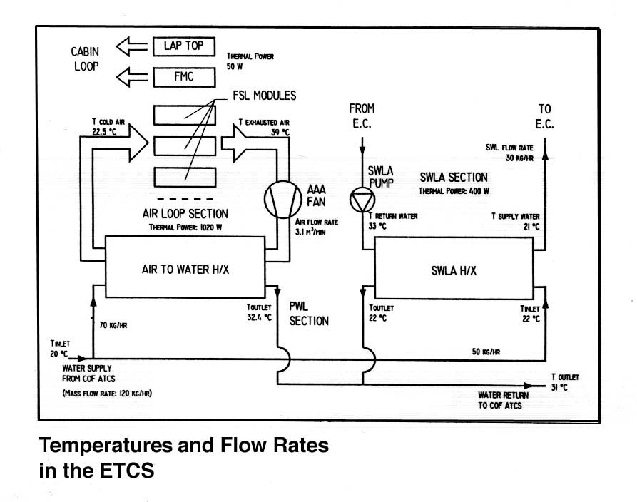
Environmental/Thermal Control Subsystem
The FSL dedicated Environmental/Thermal Control Subsystem (ETCS) is connected to the COF primary cooling loop, into which all waste heat is dissipated via the Avionics Air Assembly (AAA) and its Heat Exchanger (HX).
The subsystem provides forced air cooling to all facility modules via the related air ducts connected to the AAA, with the exception of the EC's, which are cooled via the dedicated Secondary Water Loop Assembly (SWLA). The flow rate of the SWLA is adjustable via the pump control. The SWLA temperature regulation allows a precision of ±3 K, while a higher precision (±0.1 K) is achieved with the Peltier elements (their drivers (2) are integrated in the facility, the actual elements within the EC). Still higher precision regulation of the fluid cell (e.g. 0.01 K) can be achieved by specific design measures at EC level.
Flight Support Equipment (FSE) supports all payload flight operations, maintenance, and servicing in orbit.
It comprises:
| All non-permanently rack mounted equipment (including FMC's). | |
| Optical Reference Targets (ORT's). | |
| Data storage media (tapes, floppy disks). | |
| Flight spare parts (fuses, etc.) | |
| FSL specific tools and items for on-orbit servicing/maintenance. | |
| Consumables (cleaning agents, wipes, etc.). |
The specific purpose of the Optical Reference Targets is to support functional check-out, calibration, and set-up for the envisaged diagnostic measurements prior to the experiment runs. The ORT's will be inserted into the EC experiment volume and are normally stowed in the FSL dedicated stowage container.
Stowage Container
The FSL Stowage Container is used for stowage of parts of the FSE during launch, landing and on-orbit phases. Foam inserts are used for critical items to damp vibration loads to less than the acceptable maximum.
The FSL Work Bench is a lockable drawer that hosts the LTU during non-operational phases. During FSL operations the Work Bench is extracted and the LTU is attached to its top via corresponding restraints.
Fire Detection and Suppression Panel with Rack Main Switch Assembly
The Fire Detection and Suppression Panel (FDSP) and the Rack Main Switch Assembly (RMSA) are mandatory equipment for all facilities on the ISS. The FDSP is connected to the overall Fire Detection and Suppression System and provides means for fire detection as well as an access port for a fire extinguisher. The RMSA is the manually operated main power switch.
Data summary| Mass (incl. ISPR) | At launch | 500 kg max. |
| On station | 700 kg | |
| Dimensions | 1 ISPR | |
| Power consumption | Peak | 1750 W |
| Continuous | 1555 W\ | |
| Max. dissipation incl margin. | Primary loop | 1690 W |
| Secondary loop | 475 W | |
| Cabin air | 60 W | |
| Data traffic | COF P/L 1553 bus (low rate) | 50 Kbps |
| COF video link (high rate down link) | 2Mbps average; 32Mbps max. | |
| FSL internal bus (low rate) | 165 Kbps | |
| Max. digital data to VMU hard disk | Max. 4 channels simultaneously | 30 MBps (4 x 7.5) (with 8bit this results in 240Mbps) |
| VMU hard disk to tape recorder | Replay mode | Max. 5 MBps, this results in a pause of approx. 116min before the hard disks can be used again. |
| Max. digital dataTo tape recorder | per cartridge 35GB | |
| CCD camera to tape recorder | VMU hard disk bypassed | Max. 5 MBps, if
applicable. (e.g.: 400x400x8x30Hz=40Mbps or: 800x800x8x7.8Hz=40Mbps for 116min) |
| Video management | Image resolution | Function of field of view and camera (F.o.V. 80x80mm with 800x800 results in 0.1mm resolution) |
| Time Resolution | Function of frame rate Integer multiple/submultiple of 7.5 fps | |
| Max. recording capability standard spatial resolution 0.1mm, time resolution 33ms (uncompressed) | Camera mode: 1 source | 800x800x8bitx30Hz=240Mbps for 17.8min |
| Camera mode: sources real simultaneously | 2x 700x700x8bitx30Hz=235Mbps for 17.8min (i.e. standard resolution performance for a slightly reduced F.o.V. of 70x70mm) | |
| Compression | quantitative scientific data | A compression factor in the range between 10 to 15 seems to be applicable without an significant impact on the scientific result. Exception: Noisy images like those from the ESPI. Even for images with a good contrast the compression ratio will be limited to a range of 1 to 3. In general compression cannot be applied to those type of images. The total recording time extends automatically by the same factor, i.e. to a range of 178 to 267min or 3 to 4.5hrs! (BDPU cine camera 10min/film roll) |
| Qualitative scientific images15Hz max(Telescience) | With a raw digital data rate of 120Mbps and an average down link rate of 2Mbps, a compression factor of 60 would be necessary to perform telescience. This is not possible with the JPEG algorithm. Minimum down link rates of 4 to 6Mbps are required to perform telescience with JPEG, i.e. with a compression factor in the range of 30 to 20. This can be managed by a proper time lining or higher average rates. (Exception: ESPI, telescience cannot be performed by just applying compression, regardless which algorithm.) | |
| Typical experimen Duration (1 exp. run) | 5 to 72 hrs, this includes the whole preparation and thermal conditioning. Measurement time typically 10 to 30 min for experiments requiring 30Hz data acquisition. | |
| Crew time | Reconfiguring / maintenance / servicing | TBD |
The distinction between standard and complementary diagnostics results from the fact that standard diagnostics are permanently integrated in the facility and the complementary diagnostic equipment is integrated in the individual EC's. Consequently the former is accessible and nominally usable by all experiments, while the latter is dedicated to one specific experiment or EC only.
Standard diagnostics in the facility:
|
FMC viewing in the visual spectral range in y- and z- direction (front side and bottom side viewing) covering high speed, high spatial resolution and colour recording (for FMC details see above). | |
|
FMC viewing in the infrared spectral range. | |
|
Particle image velocimetry in xy- and xz- plane with white light and monochromatic (laser) light sheets of variable thicknesses; use of liquid crystal tracers possible for simultaneous velocimetry and thermometry (one application of a colour camera). | |
|
Front and bottom viewing via integrated electronic cameras (y- and z- direction). | |
|
ESPI for surface measurements in y- and z- directions. | |
|
ESPI in transmission mode in y- and z- direction. | |
|
Wollaston interferometry in y- and z- direction. | |
|
Schlieren observation in y- and z- direction. | |
|
Holographic interferometry in y- and z- direction. |
Notes:
|
The illumination required for the diagnostic equipment includes white light background (in y- and z- axis) and white light and monochromatic light sheets. The thickness of the light sheets is variable between 0.1 and 30 mm, thus providing also volume illumination of the fluid cell from the side (e.g. for performing photogrammetry). Scanning by light sheet across the total fluid cell volume is also possible. |
|
The above listed diagnostics allow a total of 53 different single and simultaneous diagnostic modes. This number is a theoretical figure of which the useful modes will be determined in practice by the individual experiments. |
Examples of Complementary Diagnostics in the EC's tailored to individual experiments:
|
Special interferometers, like the Mach-Zehnder and the Fizeau types dedicated to comparably small objects, i.e. with restricted F.o.V.’s . | |
|
Light Scattering Diagnostics related to small object spaces. | |
|
Laser Doppler Anemometer/Laser Doppler Velocimetry (LDA/LDV) |
related to local precision measurements of velocities.
|
High resolution dedicated sensors (pressure, temperature, etc.) | |
|
Microscopes, Endoscopes. | |
|
Special laser sources. | |
|
Compact photogrammetric camera heads for 3D measurements. |
Last Update: October
1998
For more information on the FSL please contact:
Horst Mundorf
(hmundorf@estec.esa.nl)
Project Manager for the FSL facility
Microgravity Facilities for Columbus Division
(MSM-GF)
ESA ESTEC Keplerlaan 1 - NL 2201 AZ Noordwijk ZH
|
Page
reference: 19 |
|